
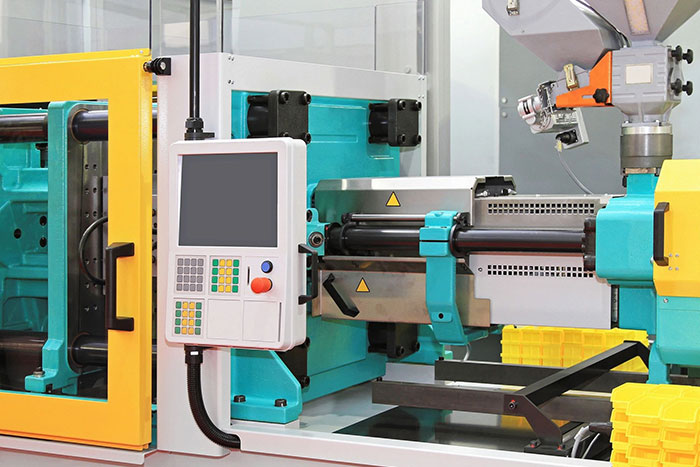
Two machines. The same mould. The same resin. One ships good parts all shift; the other throws flash on Tuesday and sink marks on Thursday. If you work in plastics, you have seen this. The difference is almost never the machine’s nameplate. It is the process window: the temperatures, pressures, speeds and times that shape each shot, and how steadily they are held.
Parameters such as melt and mould temperature, injection and holding pressure, injection speed, cooling time and clamp force are the levers that decide part quality, dimensional accuracy and cycle efficiency.[1] This guide walks through each lever, shows how it connects to the defects on your floor, and explains why holding a setpoint on a screen is not the same as controlling the process.
1. The cycle in four stages
Injection moulding is commonly described as four stages: melt filling, pressure holding, cooling, and demoulding.[2] Each stage has its own dominant parameters, and a mistake in an early stage cannot be fixed in a later one.
2. Temperature: melt, mould and material condition
Melt temperature
The right melt temperature depends on the resin, the barrel temperature profile and residence time.[1] Too low, and the melt is viscous: you risk short shots, weak weld lines and dull or incomplete surfaces. Too high, and you risk degradation, splay, burn marks and flash, because thin melt escapes at the parting line.
Academic optimisation studies point the same way. In one study of a junction box, melt temperature had the largest effect on volume shrinkage and warpage, ahead of holding time, holding pressure and cooling time.[3] In another, on an optical lens barrel, roundness and concentricity errors were driven mainly by melt temperature, packing pressure and cooling time.[4] The ranking is part-specific, but the lesson is consistent: melt temperature is rarely a minor variable.
Mould temperature
Mould temperature controls how fast the part skin freezes, and with it surface finish, crystallinity and residual stress. A hotter mould reduces moulded-in stress but lengthens cooling; uneven cooling causes warpage, twisting and shrinkage defects. Shrinkage can also continue for days after ejection, with MIT course material noting it can progress for up to 30 days,[5] so a part that measures well at the press can still move in the warehouse.
Moisture and material condition
Hygroscopic resins (nylons, PET, PC and others) must be dried to the supplier’s specification. Wet resin is a classic source of splay and brittle parts, and it changes from lot to lot and day to day. Always use the resin datasheet for drying time, temperature and target moisture.
3. Pressure and speed
Pressure in moulding is not one number. It changes through the cycle, which is why process engineers think in curves rather than setpoints.
- Injection (fill) pressure and speed push melt into the cavity. Too slow and the material freezes early; too fast and you can cause jetting, where a stream of resin snakes across the cavity and leaves visible defects.[1]
- Switchover (V/P transfer) is the point where the machine moves from velocity control to pressure control. Switching too late overpacks and causes flash; too early gives short shots or sink.
- Pack and hold pressure compensate for shrinkage as the plastic cools. MIT course notes cite typical injection-unit pressures of roughly 1,000 to 5,000 psi, with hold and pack pressure in a much higher range of about 10,000 to 20,000 psi.[5] Values depend on the machine, material and part.
- Clamp force must exceed the force that cavity pressure exerts across the projected area of the part, or the mould opens slightly and flash appears.
4. Time: fill, pack and cooling
Time parameters are easy to overlook because they are simply numbers on a timer, but they should be derived from physics, not habit.
- Pack time should be long enough for the gate to freeze. Simulation guidance describes the gate freeze time as the basis for the packing time.[6] Stop packing before the gate freezes and the part can lose material back through the gate, giving sink marks, voids and weight variation. Pack long after it freezes and you only burn cycle time.
- Cooling time is set by how long the part takes to freeze enough to eject without distortion.[6] It is one of the most critical settings for both throughput and dimensional stability; cutting it improves throughput but risks warpage.[1] Because heat must travel through the wall, thick sections dominate: cooling time grows rapidly with wall thickness.
- Cycle time is the sum of the stages. In MIT’s illustrative example, part cooling and pack/hold are the two largest blocks of the cycle.[5] That is why the tempting shortcut is always to trim cooling, and why it so often returns as warpage.
5. From defect to parameter: a working map
A starting point for troubleshooting. Always change one variable at a time, and record before and after.
| Defect | Likely parameter drivers | First checks |
|---|---|---|
| Short shot | Low fill pressure or speed, low melt temperature, early freeze[1] | Melt temp, fill speed, vents, switchover position |
| Flash | Overpacking, high melt temp, insufficient clamp force, worn parting line | Switchover point, pack pressure, clamp tonnage, mould wear |
| Sink marks and voids | Low pack pressure or time, early gate freeze, thick sections, hot spots[1] | Gate freeze study, pack time, local mould cooling |
| Warpage | Uneven mould temperature, short cooling, uneven packing[5] | Core vs cavity temperature, cooling time, balanced cooling lines |
| Weld line weakness | Low melt or mould temperature, slow injection[1] | Melt temp, fill speed, venting at the weld location |
| Splay | Moisture, overheated or sheared melt | Drying records, barrel profile, residence time |
| Jetting | Excessive velocity through the gate[1] | Profiled injection speed, gate design |
| Burn marks | Trapped air, very fast fill, overheated melt[6] | Venting, fill speed, melt temperature |
6. The real problem: setpoints are not the process
Most plants can tell you what the HMI setpoints should be. Fewer can tell you what actually happened in shot 41,872. Between the setpoint and the part sit many things that change on their own:
- Resin lot-to-lot viscosity and regrind ratio changes
- Moisture pick-up and dryer performance
- Ambient temperature, chiller and coolant flow variations
- Heater band, check ring and screw wear that slowly change melt quality and cushion
- Well-meaning operator tweaks on the night shift that never reach the process sheet
And the stakes are broader than one cell. Each plant differs in equipment, operators, suppliers and environment, so quality models built in one place rarely transfer cleanly to the next.
7. How Klyff helps: the four pillars
Klyff is a Manufacturing Intelligence platform that unifies plant telemetry, quality, maintenance and fleet learning. Its four modules map cleanly onto the problems above. You can deploy one or all four.
Analyzr
Entire plant in one screen. Ingests data from edge devices over MQTT, CoAP and HTTP and industrial gateways, and gives plant managers live views of throughput, OEE, FPY, alarms and asset health. For moulding, that means melt, mould, pressure and cycle data in one place, ready to be compared shot by shot and shift by shift. Live plant visibility in 2–4 weeks.
Explore Analyzr →Inspeqtr
Zero defects. Vision inspection that runs on existing cameras and edge hardware, keeps images on-prem, and Klyff reports can improve FPY by 2–4 points and catch subtle defects AOI misses. Link what the camera sees (flash, short shots, sink, splay) back to the parameters at that shot. Live in 8–12 weeks.
Explore Inspeqtr →Prescptr
Infinite uptime. Uses existing vibration, temperature and process-tag sensors to score failure risk, with Klyff targeting 30–50% less unplanned downtime on monitored assets. Think heater bands, pumps, chillers and drives that quietly pull your process out of its window. Scoring in 6–10 weeks.
Explore Prescptr →Senatr
Fleet-level learning. Share model improvements across plants while keeping raw data on site, so a defect detector proven on one press line can roll out to others in weeks, with GDPR and data-residency policies respected.
Explore Senatr →The common thread: Klyff runs AI at the edge, close to the machine, so decisions land in milliseconds without sending sensitive production data to a third party. Klyff states there is no cloud lock-in, deployment typically takes 4–8 weeks, and the platform is SOC2 certified.
A note on evidence: the figures above are Klyff’s published platform results across its customer base, not a guarantee for any specific moulding line. A short plant walkthrough is how we establish what is realistic for yours.
8. A practical checklist you can use this week
- Verify resin drying against the datasheet, and log the moisture at the hopper, not just the dryer setpoint.
- Run a gate freeze (pack time) study and a cooling study, and write the results on the process sheet.
- Record cavity pressure or hydraulic pressure peaks, cushion and fill time on every shot, and trend them.
- Check core versus cavity temperature, not just chiller supply temperature.
- Compare shift to shift. If nights and days run different parameters for the same job, find out why.
- Connect rejects to shot data. If a defect cannot be traced back to the parameters of that shot, you are troubleshooting blind.
- Review wear signals (cushion drift, recovery time, heater duty) on a regular schedule rather than after a breakdown.
See your own process through Klyff
Whether you run one press or hundreds across several sites, we’ll walk through your moulding data, your defect history and where a platform like Klyff could make the biggest difference. No generic slides.
Book a Technical Demo Schedule a Discovery CallPrefer to self-assess first? Try the Plant Survey.
Sources
- Fictiv, “Injection Molding Process Parameters.” fictiv.com
- Multi-Objective Optimization of Injection Molding Parameters for Thin-Walled Composite Connector Terminals, PMC11355605. ncbi.nlm.nih.gov
- Multi-Objective Optimization of Injection Molding Process Parameters for Junction Boxes (BP Neural Network and NSGA-II), PMC11818100. ncbi.nlm.nih.gov
- Taguchi Optimization of Roundness and Concentricity of a Plastic Injection Molded Barrel of a Telecentric Lens, PMC8512082. ncbi.nlm.nih.gov
- MIT OpenCourseWare 2.008, Design and Manufacturing II, polymer processing lecture notes (S. Kim, Spring 2004). ocw.mit.edu
- SOLIDWORKS Plastics help, “Designing the Injection Molding Process.” help.solidworks.com
- Klyff product information: klyff.com
This article is general educational guidance. Always follow your resin supplier’s datasheet and your mould and machine manufacturers’ recommendations.